The
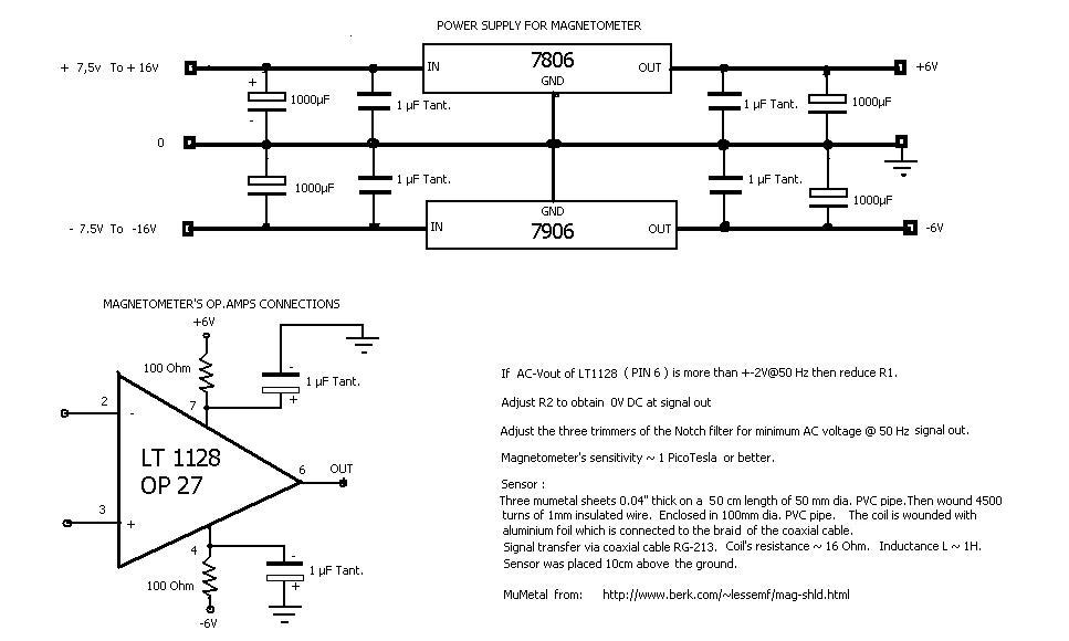
electronic circuit diagram can be seen on Picture 1
and Picture 2. It consists of amplifying stages and electronic frequency
filters.
Its
first stage consists of the operational amplifier LT1128. The alternative
voltage (in the 50Hz frequency) of the LT1128 Pin 6
should not exceed +-2V (in reference to ground); alternatively, we reduce the
value of R1.
The
second stage is a filter “Notch” in the frequency of 50Hz and consists of
two OP27.
The
three variable resistors of the filter are 20-turns “trimmers”, adjusted to
the values specified on the diagram, before placed on the circuit. When the
circuit is in operation measuring the magnetic field, the “trimmers” are
readjusted micro metrically on the original values, in order to achieve the
lowest AC voltage in the frequency of 50Hz, at the circuit output.
From
“trimmer’ R2, we should have 0 V DC at the circuit output, while from the
“trimmer” of the output stage, we adjust the value of the output signal
which we forward to the Line-In of our computer sound card.
The
capacitors C1, C2, C3, C4 are of “Silver mica” or “foil polystyrene”
type in order to maintain stable capacity during temperature variations.
All
stable resistances are of “metal film” 1% type.
Having
tested many different operational amplifiers combinations, I decided on the ones
of the diagram since they offer lower noise levels and better overall
performance on the specific circuit.
![]()